| Today |
| Workshops |
| Audio/Video |
| Electronics |
| Carputer |
| Misc |
| Other Garages |
| Contact Us |
| RainyDayGarage... |
||
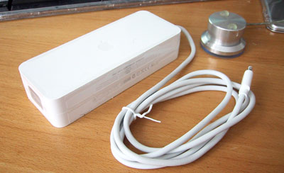
The Mac mini CPU came with an external power suppy. The Mac mini runs on 18V DC, but apparently will also work fine on 12V DC...which is what we have coming from the car's electrical system.
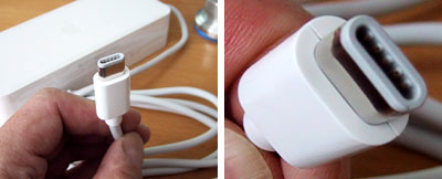
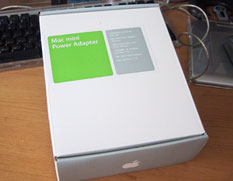
Everyone who has used the Mac mini for their carputer project has run into the same issue: how to power the CPU directly (ie: without using an AC/DC inverter). The problem is that the Mac mini uses some strange and extremely difficult-to-obtain power connector. Why? Only the Apple engineers know for sure. There is really only one option if you want to directly power the Mac mini -- cut the cord and use the connector that came with the Mac mini. About a month ago, Apple started selling the external power supply as an accessory. We got one for the connector and so we could take apart the power supply :-)
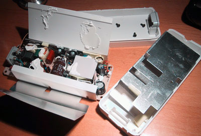
First thing we noticed about the power supply was that it was NOT meant to be taken apart. The two halves were glued together...REALLY WELL. After picking at it for about 30 minutes, we got tired of pussy footing around, brought it to the shop and cut it open with the table saw. Ah...the joy of having power tools at at the office.
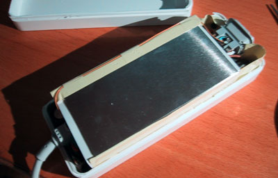
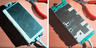
This is the end we were interested in. There was not much holding the cable to the circuit board. The assembly was attached to one side of the case by 4 phillips screws.
Once the screws were removed, the assembly was easily lifted out of the case. A quick look showed the metal shield around the unit was attached only by yellow tape.
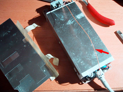
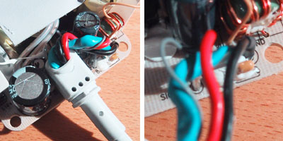
What appeared to be a ground wire (red arrow) connected the two plugs together. We carefully removed the yellow tape to free the wire.
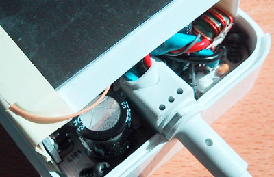
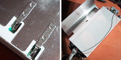
The inside shield was soldered onto the circuit board. We realized that it would be simplier to just open up the flaps rather than try to detach the shield. The metal pieces bend quite easily. We took care not to break the ground wire connecting the two ends.
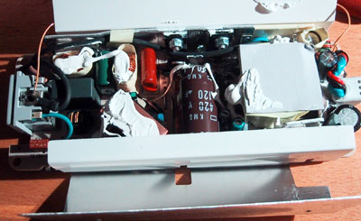
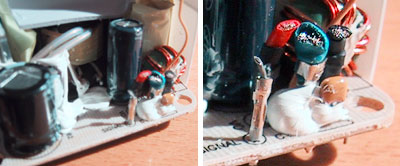
AC circuit boards are SO MUCH more messier looking than digital circuits :-) There are always all these mysterious looking coils and large capacitors all over the place. And what's with all this white goo everywhere???
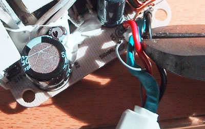
We thought about desoldering the wires from the board, but it actually made more sense just to cut it. This way, should we ever need to reattach the wires (a most unlikely scenario), at least we'll know where they go.
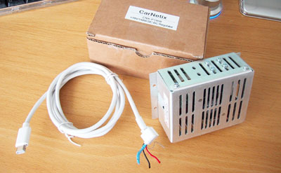
Here are the left over pieces of this project. If you want this AC power supply...it's up for auction now on EBay. Perfect for the analog geeks out there who wants to see just what makes this thing tick :-)
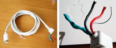
The cable is now ready for use. Since we did all this work to get it, we will attach a standard connector to the end so we can easily connect/disconnect it from the power source.
In the next article, we'll show how to connect this cable up to the Boxster's electrical system using the CarNetix DC/DC regulator. The CarNetix regulator will enable us to leave the carputer on "sleep mode" so when the ignition is turned on, the carputer will only take 3 seconds to startup.
|
Apple Mac mini AC Power Adapter Disassembly & Cable Removal |
|
In order to power the Mac mini directly from the Boxster's 12VDC battery, we needed to find a source for the Mac mini's non-standard power plug.
After unsuccessfully searching for a few months, we decided to buy another AC power adapter from Apple and remove the cable from the adapter and use it for our project. We could have just cut the cable from the adapter, but we were curious as to what was inside. So we decide to open adapter and extract the cable whole. Project Summary: 1. Difficulty - easy 2. Time - 10-30 min 3. Tools - bench saw 4. Cost - $50
The Mac mini portion of this Carputer project is divided into: Other segments of Carputer project:
iPod installations: 1. Aux Cable Install in a Porsche Drive+Play installation: 1. FirstLook 5. FirstUse Other Boxster Projects: - PVC Rear Speakers installation - Aluminum Pedals installation
|
||